Activity 14: Stereometry
here is the RQ factorization code from: http://www.cs.nyu.edu/faculty/overton/software/uncontrol/rq.m written by Michael Overton and modified by yours truly for scilab.
-oOo-
function [R,Q]= rq(A)
//% full RQ factorization
//% returns [R 0] and Q such that [R 0] Q = A
//% where R is upper triangular and Q is unitary (square)
//% and A is m by n, n >= m (A is short and fat)
//% Equivalent to A’ = Q’ [R’] (A’ is tall and skinny)
//% [0 ]
//% or
//% A’P = Q'[P 0] [P R’ P]
//% [0 I] [ 0 ]
//% where P is the reverse identity matrix of order m (small dim)
//% This is an ordinary QR factorization, say Q2 R2.
//% Written by Michael Overton, overton@cs.nyu.edu (last updated Nov 2003)
m = size(A,1);
n = size(A,2);
if n < m
error(‘RQ requires m <= n’)
end
P = mtlb_fliplr(mtlb_eye(m));
AtP = A’*P;
[Q2,R2] = qr(AtP);
bigperm = [P zeros(m,n-m); zeros(n-m,m) mtlb_eye(n-m)];
Q = (Q2*bigperm)’;
R = (bigperm*R2*P)’;
-oOo-
you can invoke the function by saving the file as ‘rq.sce’ and invoking at using getf(‘rq.sce’);
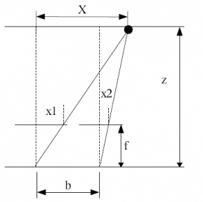
The principle behind stereometry is based on the human eye perception of depth. In humans, we perecieve depth by viewing the same object at two different angles (hence, two eyes). The lens in at position x=0 sees the object at X at different angle from x=b. Thus, by simple ratio and proportion, we can percieve depth z using the relation

where b is the separation distance of the lens, f is the focal length of the camera, and x2 and x1 are the location of the locations of the objects from the two different images.
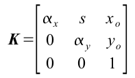
where  and
and  . However, if we are lucky enough, we may not need to compute for K if pertinent information such as f is given in the metadata of our camera. In our case, f=5.4mm. In any case, i still calculated K and found it to be

Note that xo=228 and y=329, which is near the center of a 480×640 image. Take note, however, that the image center may not be the 1/2 the image dimensions.
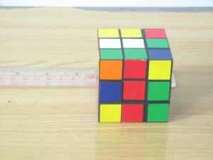
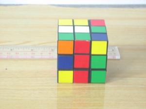
Reconstruction is done by getting as much (x,y) corresponding values in the two images. Take note that each point should have a correspondence in the other image. After which, bicubic spline splin2d and interpolation interp2d is done to create a smooth surface for our reconstruction.
After reconstruction, we result in the following image. Although it may not actually be obvious at first glance, the resulting images do resemble the front and top facade of the rubix cube. Shown below are the reconstruction viewed from different angles (the thick black lines are aides in deciphering the shape of the object).
One of the obvious error in the reconstruction is the waviness of the surface. The reason for this is the finite number of points that we have chosen for reconstruction (in my case, 24) and the way splin2d and interp interpolates points in the mesh. Another possible error is the fact that our images are 2d and not 3d, and as such, any 2 points in the 3d object may have the same (x,y) coordinate in the image plane.
I want to give myself here a 9 because even though the reconstruction along the x seems flawed, i was able to extact depth (or z values) of the images.

Leave a comment